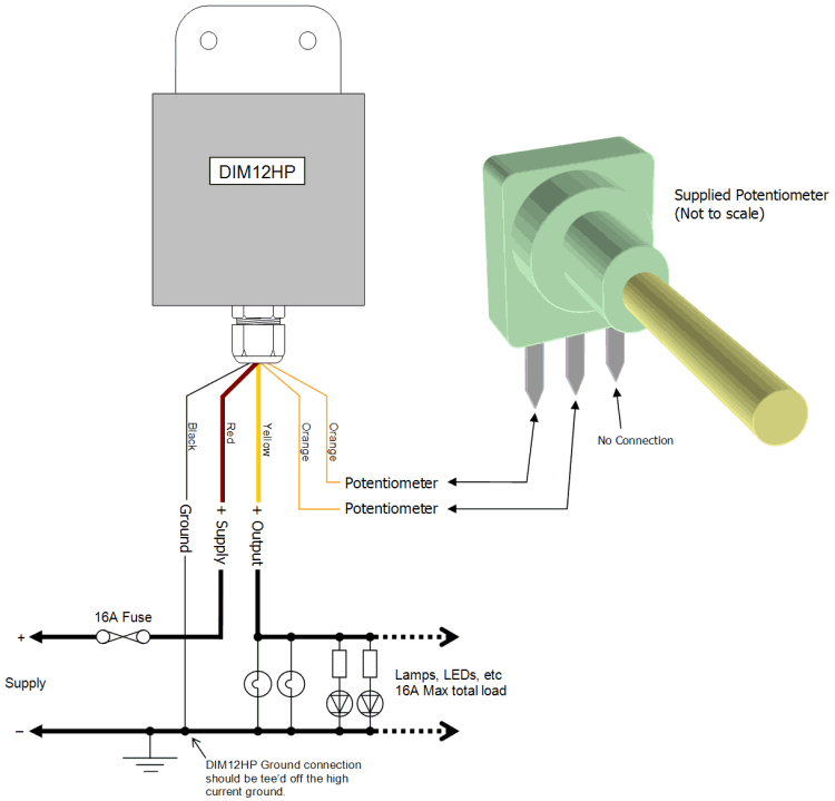
Potentiometer Motor Control Wiring Diagram
14+ Potentiometer Motor Control Wiring Diagram Pictures. Invt chf 100 factory settings | how to add motor nameplate data / मोटर नेमप्लेट डेटा कैसे जोड़ें ?? The speed of the bldc motor is controlled with a potentiometer connected to arduino.

It is controlled by another potentiometer through a arduino potentiometer is used.
But once you see how it's built, you'll quickly understand how it's done. 4 programming an arduino for servomotors. It's used in circuits a lot, such as to control the volume of music equipment, control the brightness of a light, and much more. In addition to the esc we will just use a simple potentiometer for controlling the motor speed.
0 Response to "Potentiometer Motor Control Wiring Diagram"
Post a Comment